The cuisse and poleyn
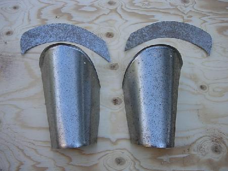
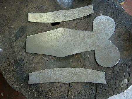
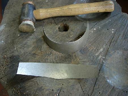
The cuisse in Project 2 was formed from a single piece of steel. Here the cuisse has an additional piece riveted to the top which imparts far greater strength. The main section is cut and shaped and the top flared using the rawhide hammer against the anvil horn. Fig. 9 shows the two main pieces with the top sections cut out but not yet shaped to fit.
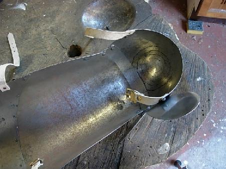
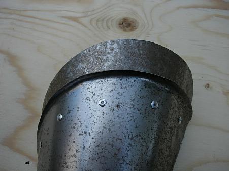
The top pieces are to have a flared outer edge parallelling that of the main sections. The flaring is imparted after the piece is curved to fit inside the lower section of the cuisse and with it riveted temporarily in place. Fig. 10 shows the top section fitted temporarily and in Fig. 11 the top edge has been flared to match that of the main piece.
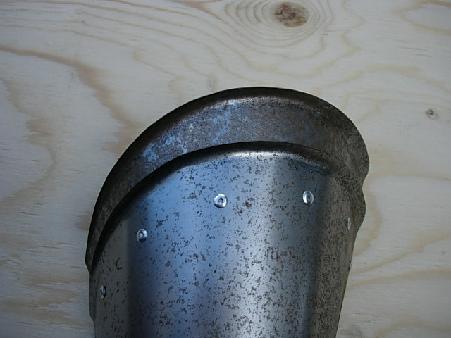
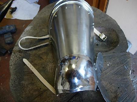
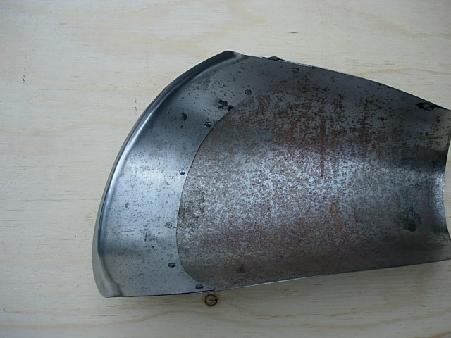
Imparting the flaring to the top section after temporarily riveting it in place ensures that the curve of the piece is not distorted during work on the edge. Fig. 12 shows the inside of the assembled cuisse with the top section closely adapted to the main body of the piece - and in Fig. 13 the temporary rivets have been removed and the pieces polished prior to final assembly.
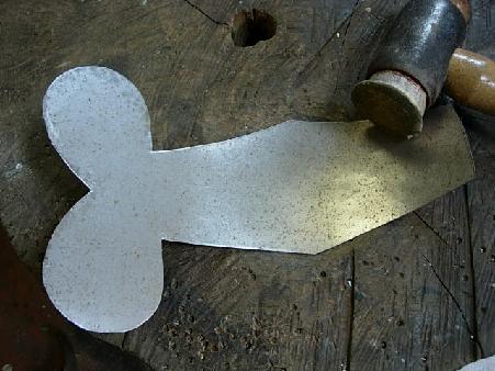
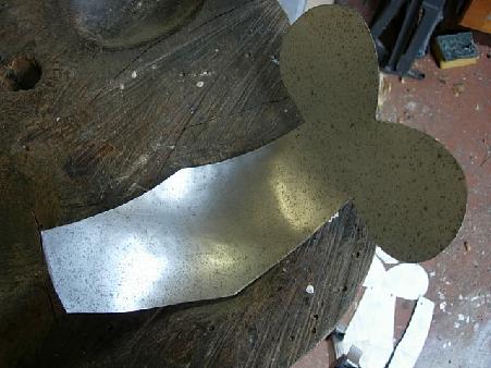
Next the pieces that will form the shell articulation at the knee are cut out - the upper lame which will articulate with the lower part of the cuisse, the poleyn and the lower lame that articulates with it to form the demi-greave. In Fig. 14 the pieces have been cut out - and Fig. 15 shows the upper lame being shaped by dishing into, first the shallow and then the intermediate depression in the stump, using the rawhide hammer.
Work on the poleyn starts by dishing the central knee cop with the rawhide hammer - Figs. 16 & 17.
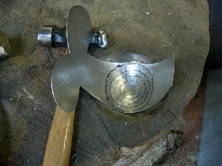
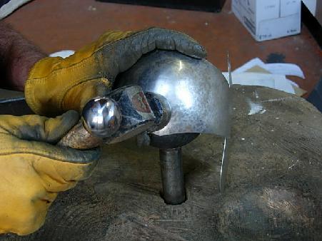
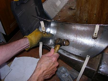
The piece is then dished into the deepest bowl on the stump using the heavy ball-ended hammer. The concentric rings which provide a guide for the hammer blows can be seen in Fig. 18. The hammer-work starts at the periphery and spirals in towards the centre, pushing the metal into the bowl of the depression. The hammer blows become heavier as work progresses towards the centre and dishing continues until the piece is as smooth as can be achieved ready for the next stage, which is planishing.
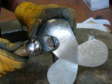
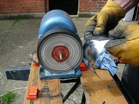
Planishing over the steel ball starts at the outside of the piece and spirals in to the centre using fairly light work with the flat side of the large hammer - with each blow just overlapping the previous one until the whole piece has been covered ( Figs. 19 & 20 ). The position of the hammer over the ball is kept static and the piece being planished moved between them.
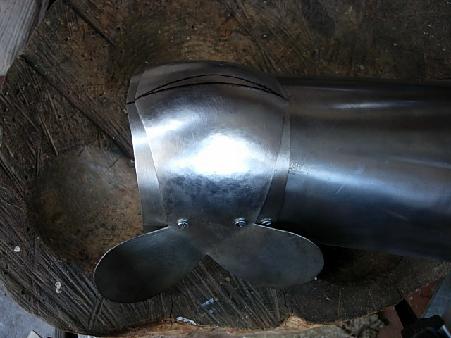
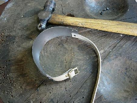
The sections are then assembled temporarily - and I am now using the more traditional method of 4mm. diameter bolts for the initial assembly rather than the aluminium 'pop' rivets ( Fig. 21 ).
With the articulation completed the piece is disassembled and the sections polished prior to the strap-work being undertaken.
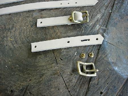
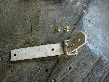
Fig. 24 shows the straps being fitted to the lower lame or demi-greave. The rivet securing the strap will be overlapped by the wing of the poleyn and so it is necessary to fit the strap before assembly. Fig. 24 shows the straps fixed to the lower lame and in Fig. 25 the poleyn is polished before final riveting.
The knee articulation can now be finally riveted together - Fig. 26 -
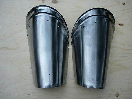
- and the final two images on this page ( Figs. 27 & 28 ) show the completed piece.